Sunday, October 31, 2010

FAQ #27 - How to setup a WebLogic cluster, Pt. 1

Introduction

This and the next FAQ will go over setting up a WebLogic cluster consisting of two Managed Servers running on a separate physical machine each. For the case of this example, each machine is running a different Linux distribution.

Main Theme

A WebLogic cluster could be setup in a number of different configurations, a WebLogic Domain in fact could be comprised of a combination of WebLogic Clusters and Managed Servers. The following is an extract from section 2 - Understanding WebLogic Server Clustering of the Oracle® Fusion Middleware Using Clusters for Oracle WebLogic Server 11g Release 1 (10.3.3) documentation:

"A WebLogic Server cluster consists of multiple WebLogic Server server instances running simultaneously and working together to provide increased scalability and reliability. A cluster appears to clients to be a single WebLogic Server instance. The server instances that constitute a cluster can run on the same machine, or be located on different machines. You can increase a cluster's capacity by adding additional server instances to the cluster on an existing machine, or you can add machines to the cluster to host the incremental server instances. Each server instance in a cluster must run the same version of WebLogic Server."

There are also several methods for setting up the clustered domain, namely using the Fusion Middleware Configuration Wizard, the Administration Console, the wlst command line utility and even programmatically. In this example we will combine the first three: we will create the domain using the Configuration Wizard and setup the domain cluster using the Administration Console and the wlst utility.

Briefly the steps involved in setting up the cluster are:

1. Install WebLogic on both physical machines
2. Create the WebLogic Domain on one physical machine
3. Configure the domain by adding Managed Servers and Machines on one physical machine
4. Copy the domain file structure to the other physical machine and enroll it to the WebLogic Domain
5. Ensure that both WebLogic Machines are operational
6. Create and configure the Cluster
7. Ensure that the Cluster is operational


1. Install WebLogic on both physical machines

The same exact version of WebLogic must be installed on both physical machines. Also, WebLogic must be installed on the same Middleware Home in both machines. This is necessary since we will be copying the domain file structure from one physical machine to the other - step 4 above.

Start by going to the Oracle WebLogic downloads page and download the latest version of WebLogic for Linux. At the writing of this, this page can be accessed by clicking here.


The 32-bit Linux WebLogic version 10.3.3. file that is downloaded is called wls1033_oepe111150_linux32.bin. For installing and administering this installation create a weblogic Linux user account and use it to login and perform the installation. Make sure that the maximum number of open files is set to 4096 for the user account.

Ensure that the wls1033_oepe111150_linux32.bin has execute permission and start the installation by typing ./wls1033_oepe111150_linux32.bin. The installation will self-unpack and present the Welcome page.


On the Choose Middleware Home Directory page accept the default Oracle/Middleware under the /home/weblogic and press Next.


On the Register for Security Updates page click Next. On the Choose Install Type page select Custom and click Next. On the Choose Products and Components page you may deselect Oracle Enterprise Pack for Eclipse and click Next. Accept the defaults on the JDK Selection page - both the Java and JRockit SDKs are selected - and click Next. On the Choose Product Installation Directories page accepts the defaults and click Next.


Verify the installation parameters on the Installation Summary page and press Next to proceed with the installation.

Now proceed with the installation of WebLogic using the exact same installation package and the steps outlined above on the other machine.


Ensure that in page Choose Middleware Home Directory the same Middleware Home is specified. In this case we will accept the default Oracle/Middleware under the weblogic user's home directory /home/weblogic.


2. Create the WebLogic Domain in one physical machine

Now, having completed the WebLogic installations on both machines, we can proceed with the creation of the WebLogic Domain. We will do this only on one of the two machines.

Start the Fusion Middleware Configuration Wizard utility - it is called config.sh and is located in the wlserver_10.3/common/bin directory under the Middleware Home (/home/weblogic/Oracle/Middleware for our installation) and on the Welcome page select Create a new WebLogic domain.


At this point accept the default products on the Select Domain Source page and click Next. On the Specify Domain Name and Location page specify the name and location of the domain. For this example we have called it clusteredDomain. On the Configure Administrator User Name and Password page specify the weblogic administrator password. Accept the appropriate startup mode and JDK on the Configure Server Start Mode and JDK page and click Next. On the Select Optional Configuration page select Administrator Server only. We will create the Managed Servers, Machines and Clusters later on using the Administration Console.


On the Configure the Administration Server page you can accept the defaults for the administration server  Name and Listen port and click Next. Verify your selections on the Configuration Summary page and when ready click on Create to proceed with the creation of the domain.


The Configuration Wizard proceeds with the creation of the domain under the path specified, which defaults to user_projects/domains under the Middleware Home. Once the domain is created successfully, we can start it by running the startWebLogic.sh script in the user_projects/domains/clusteredDomain. Verify that the domain is started successfully by observing the logs in the terminal window.


3. Configure the domain by adding Managed Servers and Machines in one physical machine

With the domain running we can proceed with the creation of the Managed Servers and Machines using the WebLogic Administration Console. So, start your browser and go to the Administration Console by specifying its address as: http://machine1:7001/console ,where machine1 is the ip address or host name of the machine that you used in step 2 above to create the Administration Server. This should display the Administration Console login form.


Enter the server administration name and password you specified in step 2 when creating the domain - username defaults to weblogic - and click Log In to login.

The first thing that we need to do now is to create the managed servers. Using the Domain Structure tree navigate to Environment and then Servers. On the Summary of Servers screen Configuration tab click on the New button to create a new Managed Server.


On the Create a New Server screen specify the Server Name, Server Listen Address and Server Listen Port. For the Server Listen Address specify the address of the first physical machine. You can click Next to verify your input and finally Finish to proceed with the creation of the Managed Server.


The Administration Console proceeds with the creation of the server. When done displays a success message in the Messages area and the server is shown in the Summary of Servers table in a SHUTDOWN state.


Repeat the steps above to create the Managed Server sunning on the other physical machine. Make sure that you specify the Server Listen Address of the other physical machine.


Now that the Managed Servers have been created we will proceed with the creation of the WebLogic Machines - one for each physical machine - and assign the Managed Servers to them.

Using the Domain Structure tree navigate to Environment and then Machines. On the Summary of Machines table click on the New button to create a new WebLogic Machine.


On the Create a New Machine page specify the name of the first machine and click OK to create the Machine.


A success message in the Messages should indicate the successful creation of the Machine and the Machine will be available in the Summary of Machines table.


Now, click on the newly created Machine and then on the Node Manager tab under the Configuration tab. The node manager will be used on each physical machine to start the Managed Servers. On this tab we need to properly configure the node manager parameters. Make sure that the Type is set to Plain and that the Listen Address corresponds to the ip address of the physical machine where this Machine's node manager is running. You can leave the port to the default 5556. Don't forget to click on the Save button to save your settings.
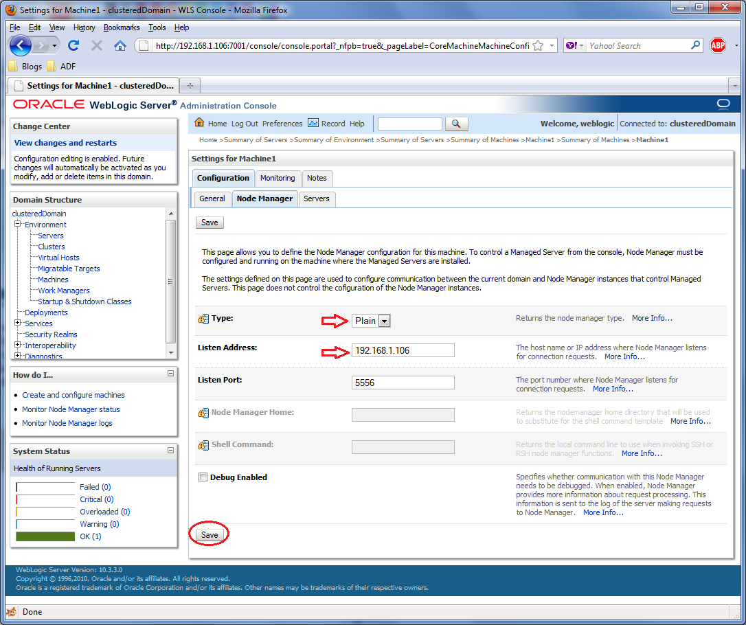

Verify that your settings were set successful by observing the Messages area.

Now you will need to assign the appropriate Managed Server to the Machine. You do this by clicking on the Servers tab under the Machine Configuration tab and then the Add button.


In the Add a Server to Machine page ensure that the appropriate Managed Server - the one that corresponds to this Machine - is selected in the Select a server choice list. Click Next or Finish to proceed with the server assignment.


The Managed Server should be assigned successfully and should be displayed in the Servers table for this Machine.


Now repeat the steps above to create a WebLogic Machine for the second physical machine. Make sure that you configure the Machine correctly and assign the appropriate Managed Server to it.


Now with the WebLogic Machines created and configured we can start the node manager on the machine. Remember that we are still working on the same machine where we run the Configuration Wizard in the first place. It can be started by running the startNodeManager.sh script in the wlserver_10.3/server/bin directory under the Middleware Home. Before starting it, go over the start-up parameters specified in the nodemanager.properties configuration file in the wlserver_10.3/common/nodemanager directory and verify that it is not configured for SSL by ensuring that the SecureListener parameter is set to false. Once started the terminal window should indicate that the node manager is  running and listening to the port configured.


To verify that the node manager is reachable by the WebLogic Machine, return to the Machines page in the Administrator Console and on the Summary of Machines table click on the first Machine - Machine1 in this case the one we are currently configuring. Click on the Monitoring tab and observe in the Node Manager Status tab that the node manager Status is Reachable.


Conclusion

This concludes this first part of setting up the cluster. On the next and final part we will continue with the setup of the second physical machine, verify that both WebLogic Machines are operational, create, configure and start the WebLogic cluster.

Until the next time, keep on JDeveloping!


Friday, October 22, 2010

FAQ #26 - How to Install JDeveloper on Linux

Introduction

A recent post on OTN related to the installation of JDeveloper on Linux is the inspiration for this FAQ. Let's go over the installation then and discover on the way how difficult or - as it turns out - how easy it is.

Main Theme

Start by downloading the latest version of JDeveloper - at the writing of this, it is 11.1.1.3.0 - from the Oracle JDeveloper Downloads web page. This download page can be accessed directly by typing the following address on your browser: http://www.oracle.com/technetwork/developer-tools/jdev/downloads/soft11-098086.html.


Once the download is done, open a terminal window and go to the directory where the installation package file resides. Ensure that you have given read and execute permissions to the installation auto-extraction package file and start its execution by typing ./jdevstudio11113install.bin, where jdevstudio11113install.bin is the name of the downloaded installation package filename. This will start the unpacking of the installation package and upon completion it will present the Welcome installation page.


Note that if you are having trouble seeing the Welcome page in graphical mode, ensure that the $DISPLAY environment variable is set correctly.

Click Next to proceed to the Choose Middleware Home Directory page and possibly accept the default Middleware Home Directory proposed by the installation program, namely Oracle/Middleware.


In the Choose Install Type page you can choose Complete to install all available components, that is JDeveloper, ADF support and the WebLogic Server. This would be fine, unless you want to selectively install certain components only.


Click Next and confirm the installation directories in the Confirm Product Installation Directories page. Confirm and click Next once more to proceed to the Installation Summary page.


Review the installation summary and when ready press Next to proceed with the installation.


The installation will start and upon a successful installation you should see the Installation Complete page. Uncheck the Run Quickstart checkbox and click Done to exit.


That's all there is to it.

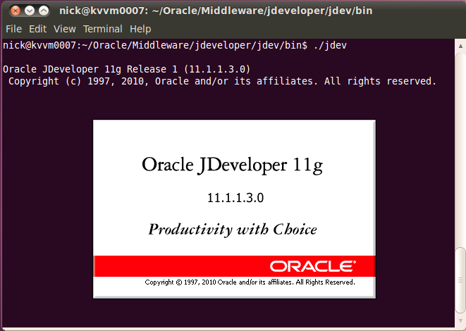
To start JDeveloper, go to the /jdeveloper/jdev/bin directory under the Middleware Home you selected during the installation and type ./jdev


JDeveloper should start.


You are know ready for developing your applications on Linux using JDeveloper. To make things easier create a shortcut to the specific file on your Linux desktop if you prefer.

Conclusion

As it turns out, installing JDeveloper on Linux is very simple. Simply download the Linux version of the JDeveloper installation package and run it. Follow the directions presented during the installation and when done, start JDeveloper by running the jdev executable in the /jdeveloper/jdev/bin directory.

Until the next time, keep on JDeveloping (on Linux)!


Friday, June 11, 2010

FAQ #25 - How to get started with SOA Suite 11g R1, Pt. 4

Introduction

In this part of the How to get started with SOA Suite 11g R1 series we will conclude the EmployeeInquirer composite by wiring the Web Service binding to the Database Adapter using a Mediator component. We will also deploy the composite to WLS and test it using Enterprise Manager.

Main Theme

Defining the transformations using a Mediator component

Open the EmployeeInquirer project and bring up the composite Design screen. The Web Service binding and the Database Adapter should be displayed on the Exposed Services and on the External Services part of the design canvas respectively. From the Component Palette grab a Mediator component and drop it on the Components section of the composite. Enter RouteRequest for the Name of the mediator and click OK.


The composite design screen should now look as it is shown below:


Now that all components have been laid out on the screen we can wire them together to define their interactions. First we will wire the Web Service to the Mediator. Click on the green binding arrowhead icon on the top right of the Web Service and drag it to the left of the Mediator. Similarly wire the Mediator to the Database Adapter by clicking on the green arrowhead icon at the right of the Mediator and dragging it to the Database Adapter. When you are done the composite should look like this:


Now that the components are wired, we will add the transformation of the request/reply messages to the Mediator. We do this by double-clicking on the Mediator component. Doing so will bring up the Mediator editor.


We will use the editor to define the XSLT transformations to both the request and reply messages, so click on the transformation icon next to the Transform Using combo - pointed above by the red arrow - to bring up the Request Transformation Map dialog.


Click on the Create New Mapper File radio button and click OK. This will open the XSLT mapping editor.


To map the employeeId from the source - left side - to the target - right side, grab the employeeId from the source side and drop it on the employeeId on the target side. The resulting mapping should look like this:


Now save the mapping and close the mapping editor. Back on the Mediator editor repeat the mapping process for the reply.


On the Reply Transformation Map dialog click on the Create New Mapper radio and click OK.


This will open the XSLT mapping editor for the reply. Map the firstName and lastName elements from the source to the destination. The result mapping is shown below:


This concludes the definition of the Mediator and concludes the project. Next we need to setup the database resource for the Database Adapter and deploy the composite to WebLogic.

Creating the database resources in WLS

Creating the data source

The database resources are required by the Database Adapter in order to access the HR schema in the database. First we need to define the data source, so start WLS and log in to the Administration Console. Navigate to Services | JDBC | Data Sources using the Domain Structure tree on the left and click the New button on the Data Sources table to create a new data source.


In the Name field enter hrDatabase. For the JNDI Name enter jdbc/hrDatabase. Select the Database Type and click Next.


On the next screen select the Database Driver and click Next.


On the Transaction Options screen click Next. On the Connection Properties screen enter the database connection information for the HR schema and click Next.


On the Test Database Connection screen click the Test Configuration button to test the connection. If all is OK a Connection test succeeded message will be displayed. Click Next to continue.


On the Select Targets screen select your SOA server and click Finish to complete the creation of the data source.


WLS will create the data source and update the Data Sources table showing the hrDatabase data source you just created.


Creating the connection pool

Next we will create a connection pool for the DbAdapter application. Since DbAdapter uses a deployment plan, you will first need to create a directory on your physical SOA server machine to contain it. I have created under the %SOA_HOME%\soa directory and I called it DBPlan. The explicit path is C:\Oracle\Middleware\Oracle_SOA1\soa\DBPlan.

Using the WLS Administration Console click on the Deployments node of the Domain Structure tree and click on the DbAdapter application shown in the Deployments table.


On the Settings for DbAdapter screen click on the Configuration tab and then on the Outbound Connection Pools tab. Click New to create a new pool.


Select the javax.resource.cci.ConnectionFactory radio button and click Next.


On the JNDI name for Outbound Connection Instance screen enter the JNDI name as you have entered it for the Database Adapter definition in the EmployeeInquirer project. To ensure that it is entered correctly, return to JDeveloper, double-click on the Database Adapter in the composite and copy it from the Service Connection page.


After you paste it on the JNDI Name field click Finish.


At this point you will be asked for the deployment plan location. Enter the path that you created earlier and enter Plan.xml for the deployment plan and click OK. Confirm the deployment plan name in the Overview tab.


Now edit the connection pool you just created to associate it with the data source previously created. Click on the Configuration tab and then on the Outbound Connection Pools tab. Expand the javax.resource.cci.ConnectionFactory connection factory and click on the eis/DB/HrConnection instance.


On the Outbound Connection Properties page enter the data source name - jdbc/hrDatabase - in the Property Value field of the xDatabaseSourceName Property Name and click Save.


Finally we will need to  update the DbAdapter application. Select Deployments from the Domain Structure tree and select the DbAdapter application. Click Update to update the application.


In the Update Application Assistant page select the Redeploy this application using the following deployment files: radio button and click Finish.


If all went well you should see these success messages:


Deploying the composite

Now we can deploy the composite to WLS. Create a connection to WLS, right-click on the project in the Application Navigator and select Deploy.


In the Deployment Action page of the Deploy wizard select Deploy to Application Server.


Click Next on the Deploy Configuration page. Select your WLS connection on the Select Server page and click Next. On the SOA Servers select your SOA server and click Next.


Verify the deployment summary on the Summary page and click Finish to start the deployment. If everything went OK you should see a BUILD SUCCESSFUL message in the SOA Log window.


The Deployment Log window should also indicate that the deployment went OK.


Testing the composite

To test the composite log in to the Enterprise Manager Fusion Middleware Control and click on the EmployeeInquirer composite on the SOA navigation tree. Then click on the Test tab.


On the Test Web Service page go the bottom of the page to the Input Arguments section and enter an Employee Id value - let's say 100, for the EmployeeId element of the request. Then click on the Test Web Service button.


The web service is executed and if everything goes OK the response will be shown on the Response tab.


This concludes our introduction to SOA Suite 11g.

Conclusion

In this series of posts we've seen how to get started with the SOA Suite 11g, from its installation to composite development - utilizing some of the basic components in JDeveloper, to testing the composite using Enterprise Manager Fusion Middleware Control. This just scratched the surface. SOA Suite is a vast technology with much more to offer.

Until the next time, keep on JDeveloping!


Code

http://code.google.com/p/jdeveloperfaq/downloads/detail?name=JDeveloperFAQNo25.rar&can=2&q=


Related Posts Plugin for WordPress, Blogger...